Circuito en Serie y en Paralelo
series and parallel circuit
Circuito en serie es una configuración de conexión en la que los bornes o terminales de los dispositivos se conectan secuencialmente. La terminal de salida de un dispositivo se conecta a la terminal de entrada del dispositivo siguiente, Siguiendo un símil hidráulico, dos depósitos de agua se conectarán en serie si la salida del primero se conecta a la entrada del segundo. Una batería eléctrica suele estar formada por varias pilas eléctricas conectadas en serie, para alcanzar así el voltaje que se precise.
Series circuit connection is a configuration in which the terminals or terminal devices are connected sequentially. The output terminal of a device is connected to the input terminal of the next device, Following a hydraulic analogy, two water tanks connected in series if the first output connected to the input of the second. An electric battery usually consists of several electrical cells connected in series, thus achieving the voltage required.

Circuito paralelo es una conexión donde los bornes o terminales de entrada de todos los dispositivos conectados coincidan entre sí, lo mismo que sus terminales de salida.
Siguiendo un símil hidráulico, dos tinacos de agua conectados en paralelo tendrán una entrada común que alimentará simultáneamente a ambos, así como una salida común que drenará a ambos a la vez. Las bombillas de iluminación de una casa forman un circuito en paralelo.
Parallel circuit is a connection where the terminals or input terminals all connected devices match each other, as well as its output terminals.
Following a comparison hydraulic water two water tanks connected in parallel have a common inlet feed them simultaneously, and a drain common output both at once. Light bulbs of a house form a parallel circuit.
Following a comparison hydraulic water two water tanks connected in parallel have a common inlet feed them simultaneously, and a drain common output both at once. Light bulbs of a house form a parallel circuit.

Union Flare
La union Flare es muy utilizada en refrigeracion para unir tuberias por medio de tuercas y un niple en ocaciones se utiliza cinta teflon para prevenir fugas.
Enseguida les enseñare el proceso de Union Flare.

Flare Union
Flare union is widely used in refrigeration for joining pipes by means of nuts and a nipple on occasion used teflon tape to prevent leaks.
Then teach them the process of Flare Union.
First place in the tube nut (the nut has to be tailored to the tube either 1/4, 3/8, 5/16 or as they're going to use)
Make a abellanado in the tube with a abellanador or flaring commonly called holding the tube with a press.
Since the tube is abellanado do the same with the other tube.
To warn of a leak cover the nipple threads with Teflon tape.
Connect the pipe nipple (the nipple has to be tailored to the nuts and that is Male / Male).

Enseguida les enseñare el proceso de Union Flare.
- Primero colocar la tuerca en el tubo(la tuerca tiene que ser a la medida del tubo ya sea 1/4, 3/8, 5/16 o la medida que vallan a usar)
- Hacer un abellanado en el tubo con un abellanador o abocinador comunmente llamado sosteniendo el tubo con una prensa.
- Ya que el tubo este abellanado hacer lo mismo con el otro tubo.
- Para prevenirnos de una fuga cubrir la rosca del niple con la cinta teflon.
- Unir los tubos con el niple(el niple tiene que ser de la medida de las tuercas y que sea Macho/Macho).

Flare Union
Flare union is widely used in refrigeration for joining pipes by means of nuts and a nipple on occasion used teflon tape to prevent leaks.
Then teach them the process of Flare Union.
First place in the tube nut (the nut has to be tailored to the tube either 1/4, 3/8, 5/16 or as they're going to use)
Make a abellanado in the tube with a abellanador or flaring commonly called holding the tube with a press.
Since the tube is abellanado do the same with the other tube.
To warn of a leak cover the nipple threads with Teflon tape.
Connect the pipe nipple (the nipple has to be tailored to the nuts and that is Male / Male).

Vacio, Detectar fuga por vacio, Carga de refrigerante
Vacuum, vacuum detect leakage, refrigerant charge
Vacío:
El vacío se hace a un sistema después de darle un mantenimiento o repararlo.
Hacer el vacío es importante para limpiar el sistema y prevenir un daño a algunos de los componentes.
Esto hace que la tubería este libre de humedad, suciedad o aire que se halla infiltrado.

Nota: Para purgar la manguera de servicio se abre la válvula donde se conecta la manguera de servicio por tan solo unos segundos ocacionando un remolino y expulsando todo el aire que contiene el maniful de servicio. Tambien se puede purgar de tal forma que solo abre la válvula del manometro de alta para que salga el refrigerante por la maguera de alta(Roja), asi expulsando el aire que contenia adentro.
Todos estos procesos son seguidos por lo que despues de hacer vací, checar si hai fuga, despues si no hay fuga, cargar refrigerante antes de que se abra la valvula del manometro de baja hacer la una purga y despues ya que todos estos procesos sean realizados cargar refrigerante.
Vacuum:The vacuum system is done after giving a maintenance or repair.Create a vacuum is important to clean the system and prevent damage to some of the components.This makes the pipe is free from moisture, dirt or air is infiltrated.1.Observe the oil pump vacuum.2.Connect the service hose (yellow) to the vacuum pump.3.Connect lower hose (blue) to the service valve system.4.Abrir valve low gauge.5.Encender vacuum pump.6.Esperar 15 to 20 minutes after the low-gauge reads 0.Ayan 7.Ya once past the suggested time to close the gauge valve down, and wait a while to see if the low pressure gauge needle rises. If the needle goes up or down to 0 is that the system is leaking.8.Si the system does not have to remove the drain hose down the system.Refrigerant charge:1.Connect lower hose (blue) to the service valve system.2.Connect the service hose (yellow) to the coolant tank.3.Purgar the service line to pull the air trapped in the hose.4.Abrir valve low pressure gauge.5.Verificar pressure and the kilograms will use the system6.Encender system7.Verificar the low dial gauge between 10 and 15 pounds, if so is that the system has enough refrigerant.
Check the oil level of the vacuum pump.
Connect the service hose (yellow) to the vacuum pump.
Connect the hose from low (blue) to the service valve system.
Opening the lower valve gauge.
Turn on vacuum pump.
Wait 15 to 20 minutes after the gauge reads low of 0.
And once past the suggested time ayan close the gauge valve down, and wait a while to see if the low pressure gauge needle rises. If the needle goes up or down to 0 is that the system is leaking.
If the system does not have to remove the drain hose down the system.
Refrigerant charge:
Connect the hose from low (blue) to the service valve system.
Connect the service hose (yellow) to the coolant tank.
Purge the service line to pull the air trapped in the hose.
Open the valve on the low pressure gauge.
Check the pressure and the kilograms will use the system
Turn on the system
Verify that the dial gauge low 10 to 15 pounds, if so is that the system has enough refrigerant.
Note: To purge the service hose valve is opened where the hose connects service for only a few seconds ocacionando a whirlpool and expelling all the air in the maniful service. Also may be purged so that only opens the valve high pressure gauge for the coolant exit by maguera high (Red), thus expelling the air contained inside.All these processes are followed by what to do after Vaci check if leakage hai, then if there is leakage, refrigerant charge before you open the valve of the low pressure gauge to the purge and then as all these processes are performed refrigerant charge.
El vacío se hace a un sistema después de darle un mantenimiento o repararlo.
Hacer el vacío es importante para limpiar el sistema y prevenir un daño a algunos de los componentes.
Esto hace que la tubería este libre de humedad, suciedad o aire que se halla infiltrado.
- Checar el nivel de aceite de la bomba de vacío.
- Conectar la manguera de servicio(Amarilla) a la bomba de vacío.
- Conectar la manguera de baja (Azul) a la válvula de servicio del sistema.
- Abrir la válvula del manómetro de baja.
- Encender bomba de vacío.
- Esperar de 15 a 20 minutos después de que el manómetro marque a bajo de 0.
- Ya una vez que ayan pasado el tiempo sugerido cerrar la válvula del manómetro de baja, y esperar un cierto tiempo para ver si la aguja del manometro de baja sube. Si sube la aguja o llega a 0 es por que el sistema tiene una fuga.
- Si el sistema no cuenta con fuga retirar la manguera de baja del sistema.
- Conectar la manguera de baja(Azul) a la válvula de servicio del sistema.
- Conectar la manguera de servicio(Amarilla) al tanque de refrigerante.
- Purgar la linea de servicio para tirar el aire atrapado en la manguera.
- Abrir la válvula del manometro de baja.
- Verificar las presiones y los kilogramos que va a utilizar el sistema
- Encender el sistema
- Verificar que el manometro de baja marque entre 10 y 15 libras, si es asi es por que el sistema tiene suficiente gas refrigerante.
Nota: Para purgar la manguera de servicio se abre la válvula donde se conecta la manguera de servicio por tan solo unos segundos ocacionando un remolino y expulsando todo el aire que contiene el maniful de servicio. Tambien se puede purgar de tal forma que solo abre la válvula del manometro de alta para que salga el refrigerante por la maguera de alta(Roja), asi expulsando el aire que contenia adentro.
Todos estos procesos son seguidos por lo que despues de hacer vací, checar si hai fuga, despues si no hay fuga, cargar refrigerante antes de que se abra la valvula del manometro de baja hacer la una purga y despues ya que todos estos procesos sean realizados cargar refrigerante.
Vacuum:The vacuum system is done after giving a maintenance or repair.Create a vacuum is important to clean the system and prevent damage to some of the components.This makes the pipe is free from moisture, dirt or air is infiltrated.1.Observe the oil pump vacuum.2.Connect the service hose (yellow) to the vacuum pump.3.Connect lower hose (blue) to the service valve system.4.Abrir valve low gauge.5.Encender vacuum pump.6.Esperar 15 to 20 minutes after the low-gauge reads 0.Ayan 7.Ya once past the suggested time to close the gauge valve down, and wait a while to see if the low pressure gauge needle rises. If the needle goes up or down to 0 is that the system is leaking.8.Si the system does not have to remove the drain hose down the system.Refrigerant charge:1.Connect lower hose (blue) to the service valve system.2.Connect the service hose (yellow) to the coolant tank.3.Purgar the service line to pull the air trapped in the hose.4.Abrir valve low pressure gauge.5.Verificar pressure and the kilograms will use the system6.Encender system7.Verificar the low dial gauge between 10 and 15 pounds, if so is that the system has enough refrigerant.
Check the oil level of the vacuum pump.
Connect the service hose (yellow) to the vacuum pump.
Connect the hose from low (blue) to the service valve system.
Opening the lower valve gauge.
Turn on vacuum pump.
Wait 15 to 20 minutes after the gauge reads low of 0.
And once past the suggested time ayan close the gauge valve down, and wait a while to see if the low pressure gauge needle rises. If the needle goes up or down to 0 is that the system is leaking.
If the system does not have to remove the drain hose down the system.
Refrigerant charge:
Connect the hose from low (blue) to the service valve system.
Connect the service hose (yellow) to the coolant tank.
Purge the service line to pull the air trapped in the hose.
Open the valve on the low pressure gauge.
Check the pressure and the kilograms will use the system
Turn on the system
Verify that the dial gauge low 10 to 15 pounds, if so is that the system has enough refrigerant.
Note: To purge the service hose valve is opened where the hose connects service for only a few seconds ocacionando a whirlpool and expelling all the air in the maniful service. Also may be purged so that only opens the valve high pressure gauge for the coolant exit by maguera high (Red), thus expelling the air contained inside.All these processes are followed by what to do after Vaci check if leakage hai, then if there is leakage, refrigerant charge before you open the valve of the low pressure gauge to the purge and then as all these processes are performed refrigerant charge.
Filtro Deshidratador
Un filtro deshidratador por definición, es un dispositivo que
contiene material desecante y material filtrante para remover la humedad y otros contaminantes de un sistema de
refrigeración
Valycontrol, S.A. de C.V. fabrica una gran variedad de
deshidratadores para sistemas de refrigeración doméstica, comercial, industrial y aire acondicionado.
filter Drier
A filter drier by definition, is a device which
contains desiccant material and filter material to remove moisture and other contaminants from a system
refrigeration
Valycontrol, Inc. de CV manufactures a wide variety of
dehydrators for domestic refrigeration, commercial, industrial and air conditioning
Refrigerante
Un refrigerante es un producto químico líquido o gaseoso, fácilmente licuable, que es utilizado como medio transmisor de calor entre otros dos en una máquina térmica. Los principales usos son los refrigeradores y los acondicionadores de aire.
El principio de funcionamiento de algunos sistemas de refrigeración se basa en un ciclo de refrigeración por compresión, que tiene algunas similitudes con el ciclo de Carnot y utiliza refrigerantes como fluido de trabajo.
Cuando comenzaron las preocupaciones por la capa de ozono, los refrigerantes más usados eran los clorofluorocarbonos R-12 y R-22. El primero era empleado principalmente para aire acondicionado de vehículos y para pequeños refrigeradores; el segundo para aire acondicionado, refrigeradores, y congeladores comerciales, residenciales y ligeros. Algunos de los primeros sistemas emplearon el R-11 por su bajo punto de ebullición, lo que permitía construir sistemas de baja presión.
La producción de R-12 cesó en Estados Unidos en 1995, y el R-22 fue eliminado posteriormente [2010]. Se está empleando el R-134a y ciertas mezclas (que no atentan contra la capa de ozono) en remplazo de los compuestos clorados. El R-410a(comúnmente llamada por su nombre comercial Puron®) es una popular mezcla 50/50 de R-32 y R-125 que comienza a sustituir al R-22.
refrigerant
A refrigerant is a liquid or gaseous chemical, easily liquefiable, which is used as heat transfer medium between two other in a heat engine. The main uses are as refrigerators and air conditioners.
The principle of operation of some refrigeration systems is based on a compression refrigeration cycle, which has some similarities with the Carnot cycle and used as a refrigerant working fluid.
When concerns began the ozone layer, the most widely used refrigerants were chlorofluorocarbons R-12 and R-22. The first was used mainly for vehicle air conditioning and small refrigerators, the second for air conditioners, refrigerators, and freezers, commercial, residential and light. Some early systems used R-11 for its low boiling point, allowing low pressure systems build.
The production of R-12 in United States ceased in 1995, and R-22 was subsequently removed [2010]. You are using the R-134a and certain blends (not threaten the ozone layer) in replacement of chlorinated compounds. The R-410a (commonly known by its trade name Puron ®) is a popular 50/50 mixture of R-32 and R-125 begins to replace R-22.


Codigo de colores de los refrigerantes / Color code of refrigerants
| Tabla 1. Código de colores ARI para los cilindros de gas refrigerante | |
| Refrigerante Número AHSRAE | Color ARI(American Refrigeration Institute) |
| R-11 | Anaranjado (PMS 021) |
| R-12 | Blanco (PMS None) |
| R-22 | Verde Claro (PMS 352) |
| R-113 | Morado (Violeta) (PMS 266) |
| R-114 | Azul Oscuro (Marino) (PMA 302) |
| R-123 | Azul Grisáceo Claro (PMS 428) |
| R-124 | Verde Intenso (Verde DOT) (PMS 335) |
| R-125 | Marrón Mediano (Tostado) (PMS 465) |
| R-134a | Azul Celeste (Cielo) (PMS 2975) |
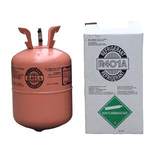
| R-401A | Rosa Claro (PMS 177) |
| R-401 B | Amarillo Oscuro (PMS 124) |
| R-402A | Marrón Claro (Arena) (PMS 461) |
| R-402B | Verde Amarronado (Oliva) (PMS 385) |
| R-404A | Anaranjado (PMS 021) |
| R-410A | Rosa (PMS 507) |
| R-500 | Amarillo (PMS 109) |
Table 1. ARI color code for refrigerant cylinders
| Refrigerant Number AHSRAE | Color ARI (American Refrigeration Institute) |
| R-11 | Orange (PMS 021) |
| R-12 | White (PMS None) |
| R-22 | Light Green (PMS 352) |
| R-113 | Purple (Violet) (PMS 266) |
| R-114 | Dark Blue (Navy) (PMA 302) |
| R-123 | Grey Light Blue (PMS 428) |
| R-124 | intense Green (Green DOT) (PMS 335) |
| R-125 | Medium Brown (Tan) (PMS 465) |
| R-134a | Blue Sky (Sky) (PMS 2975) |
| R-401A | Light Pink (PMS 177) |
| R-401 B | Dark Yellow (PMS 124) |
| R-402A | Light Brown (Arena) (PMS 461) |
| R-402B | Brownish Green |
| R-404A | Orange (PMS 021) |
| R-410A | Pink (PMS 507) |
| R-500 | Yellow (PMS 109) |
No hay comentarios:
Publicar un comentario